Upgrading and Reconfiguring the AC Circuits
For several years now I’ve been running a Victron Quattro Inverter that is capable of handling 30A of AC input and 30A of AC output. Unfortunately the stock wiring and breakers to and from the inverter were only capable of safely supporting 20A. To accommodate the stock components I’ve been programming the inverter to restrict itself to 20A of AC input and output.
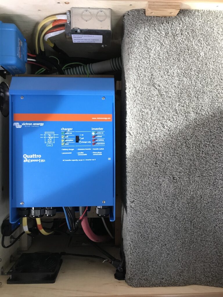
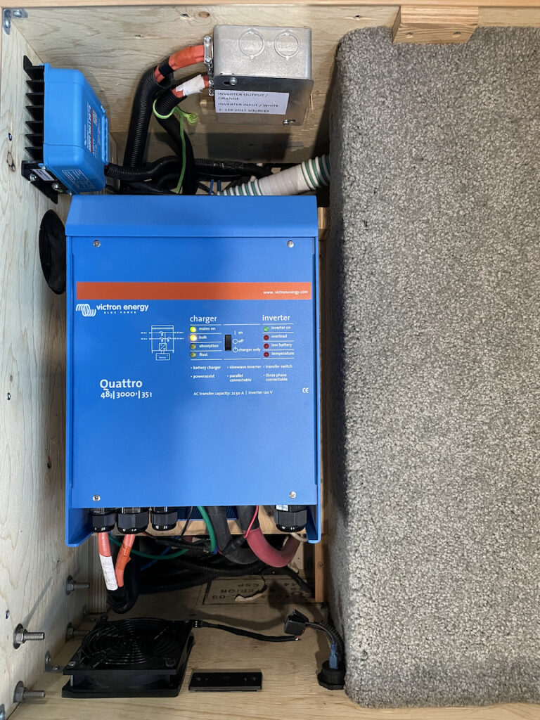
Victron 100/20 MPPT Solar Controller and Quattro 48/3000/50 Inverter/Charger/ATS in Passenger Side Ottoman with 20A Capable 12/2 Romex Wire.
I found a few hours today to remove that bottleneck by upgrading the wiring from 12/2 Romex to 10/2 Romex and installing breakers rated for 30A.
The Pleasure-Way layout in our 2017 Lexor TS made it easy to access the areas needed to make the changes.
First I disconnected the vehicle from shore power and turned off the inverter.
I then removed the cover from the circuit breaker panel and loosened the power, neutral and ground wires from the breakers. I inserted a Phillips head screwdriver through the back of the panel next to each wire to “open” the plastic tabs that were “grabbing” them. I pulled the wires out through the back side of the panel. I then opened up the junction box near the inverter, loosened the wire clamps, disconnected all of the wires and pulled them free from the box.
Next I cut two pieces of 10/2 Romex that were each 7 feet long and taped them together at 1 foot intervals with electric tape. I then covered the wires in split loom and taped it together at 1 foot intervals too. Once the new wires were ready I taped one end to the end of the old wires with some Gorilla tape and fed the new wires under the floor between the ottomans using the old ones to pull them along.
I fed the new wires through the back of the circuit breaker panel and back in to the junction box.
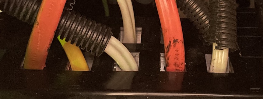
Rear of Circuit Breaker Panel with new 30A capable 10/2 Romex Wire
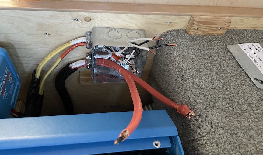
Junction Box in Passenger Side Ottoman with 30A Capable 10/2 Romex Wire.
I then cut two more 10/2 wires that were about 5 feet in length and taped them together at 1 foot intervals. I also covered them with 3/4 inch split loom and taped it together at 1 foot intervals. I once again taped the new wires to the old wires and pulled the the new wires through the bottom of the passenger side ottoman to the back of the inverter.
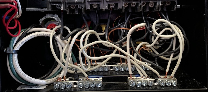
Circuit Breaker Panel with Cover Removed and new 30A Capable 10/2 Romex Wire in Place.
I then cut the wires to length and connected them to the new 30A breakers, inside the ottoman junction box and at the inverter.
Victron 100/20 MPPT Solar Controller and Quattro 48/3000/50 Inverter/Charger/ATS in Passenger Side Ottoman with 30A Capable 10/2 Romex Wire.
I also repositioned the breakers in the panel. On the left side which is assigned to Shore power I now have only two breakers. 30A power comes in to the panel through the 30A “Shore Power” breaker and then goes to the Inverter through the 30A “Inverter Input” breaker. All the other breakers are now on the right side of the panel which is assigned to the Inverter Output. With the added capacity I decided to move the Refrigerator AC power over to the Inverter side of the panel too just to make the AC/DC decision irrelevant to whether or not the refrigerator has power.
I also installed a 15A AFCI/GFCI breaker on the outlet circuit to remove the requirement to have GFCI on the first in circuit ottoman outlet. Doing so allowed us to install an outlet in that position that supports the charging of our USB devices.

AC Panel with New Circuit Breaker Configuration
When we are connected to shore power the inverter’s internal Automatic Transfer Switch (ATS) just passes the power through to the inverter side of the panel. When we are disconnected from shore power the inverter takes over and provides power from the battery.
Life on the road just got a little simpler. Everything just works.
Nice! I should do this too now that I have a 3000 watt inverter too. It sounds like you had a simpler layout than most, with no generator/shore Automatic Transfer Switch to deal with on the way to the Inverter Input. Also interesting is that in my 2019 Ascent, the cables between the inverter and the breakers run inside the van, along the back wall of the sofa, not under the van. I noticed in a PW factory tour video that in 2020 Ascents the water lines were brought inside too, along that same path behind the sofa. That’s a change I’d like to consider making myself one day.
Hi Mark,
The Victron Quattro Inverter/Charger incorporates the Generator/Shore ATS so it’s possible to remove the stock unit in the trunk. In my case I have removed the generator so I no longer use that capability. The Lexor has a raised floor between the two ottomans that makes it really simple to run things back and forth between them. I believe that it was placed there to make the floor reach a comfortable height when sitting. The higher wheel wells in the Promaster force the seating to be a little higher so the floor had to move up with them. I’ll probably make a hatch in it one day to provide even better access and to take advantage of the potential storage. I like your idea of bringing the plumbing lines inside the vehicle. Wherever they are near anything that water could short out I’d suggest running them through a conduit that could drain any potential water away from the electronics. Most manufacturers don’t take this precaution. I’ve seen a few Winnebago owners that wished they had. Murphy is real!
Bob
Ah, I forgot about the Luxor’s raised seating area… that makes perfect sense. Pulling those cables around the sofa feels like a bigger hassle for me to do. Yeah, I’m still waiting to confirm that the water lines behind the sofa thing is real in later PW models, and if so, are the AC & DC lines also in the same general area. The PW factor tour video has a few frames that I tried to interpret, and maybe got it wrong. Time will tell.