Automation
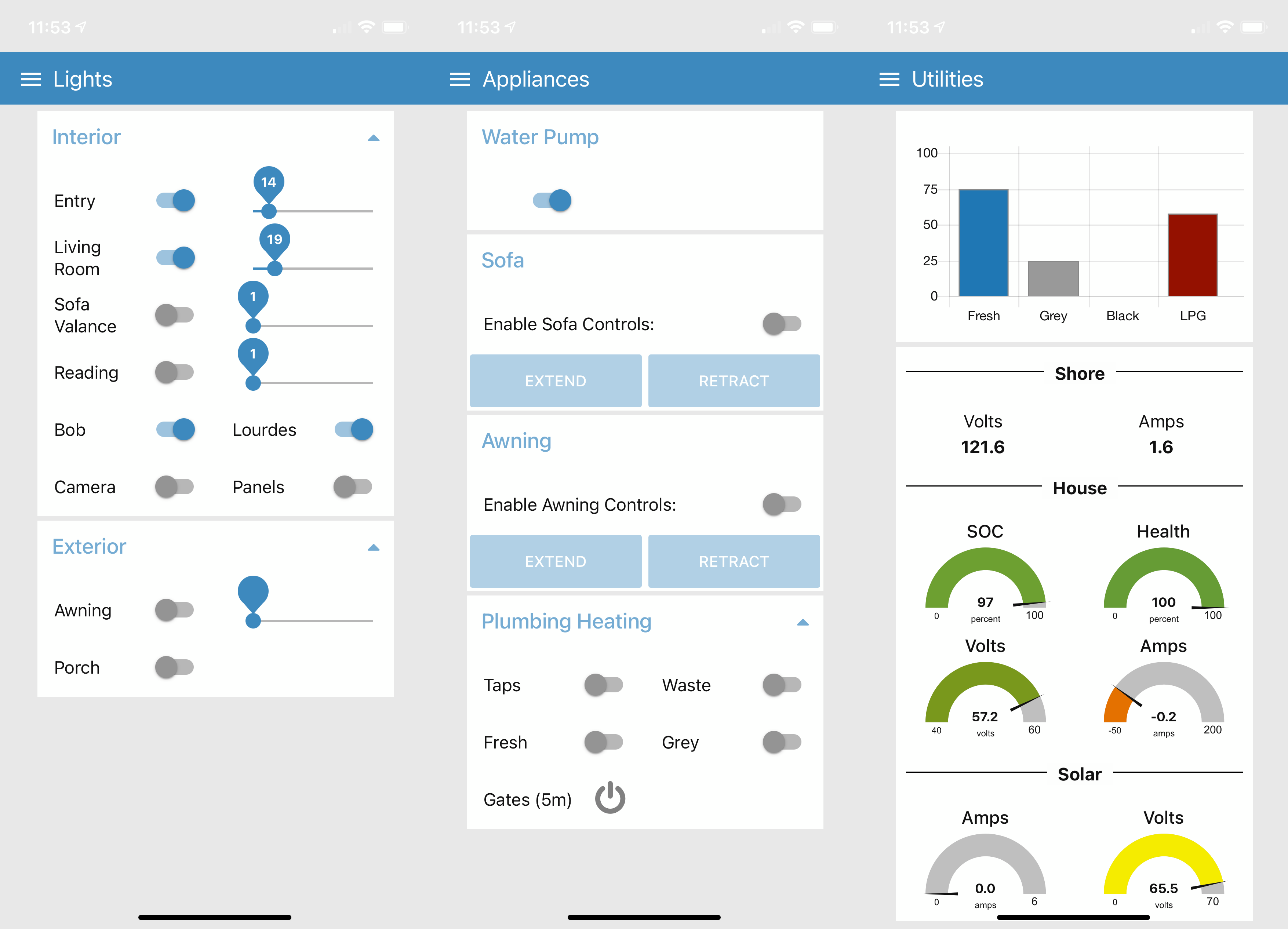
Screenshots of the Coachproxy Interface on my iPhone.
Our 2017 Pleasure-Way Lexor TS is equipped with a Spyder Controls multiplex board. The board provides centralized control and fusing for the DC appliances throughout the van. Each control panel is connected to the board with a low voltage network cable instead of the heavier copper wiring that more traditional switches and controls require.
After about 4 years of use one of our control panels started to develop some issues so I contacted Spyder to discuss our options to replace it. Our only option was to replace the panel with the same part. Rather than proceed down this path I started to research the system. I’m glad that I did because it opened up a whole new realm of control and automation.
My research led me to the open source Coachproxy project on Github and then on to a related open source project named myErvin. MyErvin is the creation of Rob Ervin. It takes the basics of Coachproxy and builds some nice automation routines around it. I have posted my basic Node-Red flow for the 2017 Lexor TS OEM configuration to the myErvin site. Even though the flow is designed for a 2017 Lexor TS it will be a good start for any Spyder Control board-equipped Pleasure-Way.
So what’s going on here? In summary, the system turns the whole Spyder board in to an MQTT-accessible device that you can control with an open source program called Node Red. Node Red is a program that allows you to program a web interface by using pre-programmed objects. It’s designed to minimize the amount of programming knowledge needed to design a web application. MQTT is the protocol behind many of the home automation systems that you may already be familiar with. It allows devices to use a typical wired or wireless ethernet network to report their status and control one another. MQTT has wide support and you’ll find that there are a lot a resources to help you learn and use it.
You may set up the system to be entirely local and benefit from the enhanced automation and control. Adding in a cellular hotspot will take it to another level by providing remote access. On our installation I used a WiFi Ranger unit that allows a choice of wireless relay, cellular service or a combination of the two to increase bandwidth. You may find out more about that installation by clicking here.
I followed Rob’s excellent instructions and had my Raspberry Pi connected to the Spyder board within a few hours. I did vary a bit from his instructions and used a Raspberry Pi 4b that I already had on hand. The Rasberry Pi 4b requires more power so I opted to connect it to the Spyder board’s main 12V power terminal in lieu of drawing power from the Spyder board’s data port connection. Its extra power and capacity are currently overkill but may come in handy for some future functions that I have in mind. The Raspberry Pi is now out of sight and is located in the ottoman space beneath the board. I’ve connected it to one of the available data ports on the back of the board.
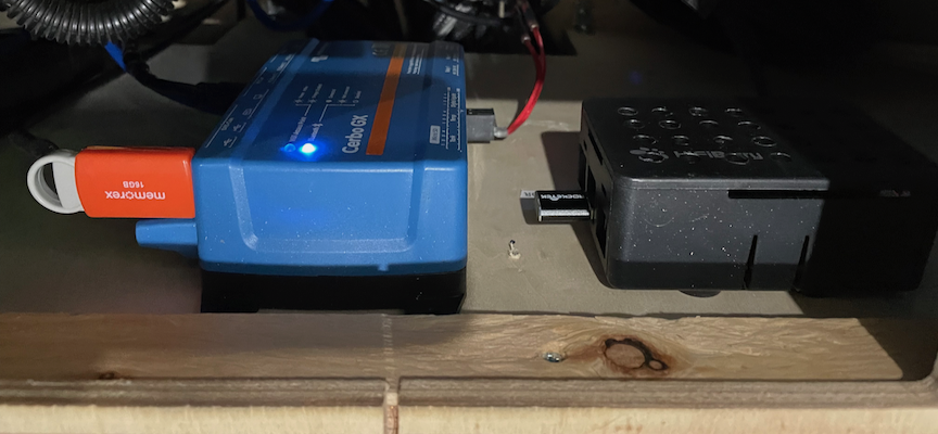
Victron Cerbo GX and Raspberry Pi running Coachproxy in Driver’s Side Ottoman Location
Next I had to spend some time learning Node-Red and how it interacted with my Pleasure-Way configured board. The primary tool that I used was MQTT Explorer on OSX. I used it to determine which command was being sent each time I pressed a button on the control panel. The pattern became fairly obvious after a few minutes and I was on my way to developing flows in Node-Red. My configuration file should help most of you avoid this step. I would still encourage you to set up and use MQTT Explorer. It will come in handy if you find that something is not responding as expected or when you are trying to add items that are not part of the OEM configuration.
The Spyder board has 3 types of cards that you may want to interact with. On my board the top card was a “dimmer card” and had all of the existing interior lights attached to its pins. The second card was an “I/O card”. The third was a “non-dimmable card” that controlled other appliances. I ended up adding a second “dimmer card” (second from the top in the image below) between the original cards 1 and 2 to add 12 more addressable ports. Each dimmable port on the stock board can control dimmable or non-dimmable items that draw up to 5A. The second card that I added can support items that draw up to 7A.
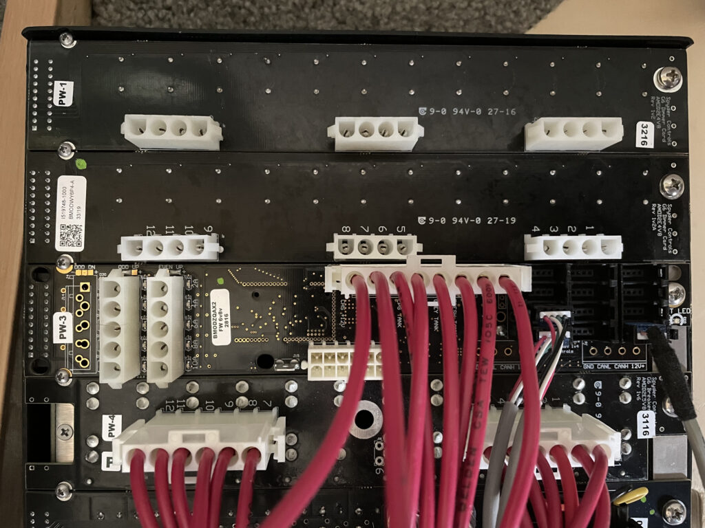
Rear of Spyder Control Board with New Dimmer Card Installed
At this point I’ve gained control of all of the items that were controlled by the original panels and have added control of the awning, awning lights, rear corner reading lights and interior camera. I’ve also upgraded my house electric system with a number of components from Victron and have incorporated them in to the interface through the Victron Cerbo GX’s built in MQTT server. Next on my list are the Belair A/C, MaxxAir ceiling fan, Truma water heater and Atwood/Dometic heater. I’ll share the details of those additions in later posts.
The project has really added some nice functionality and convenience to life in our van. Neither one of us uses the built in panels very often now. It’s more convenient to use our iPhones, iPads or Siri.
Parts List:
Systems:
These are the basic system requirements:
CanaKit Raspberry Pi 3 B+ (B Plus) Starter Kit (32 GB EVO+ Edition, Premium Black Case)
https://copperhilltech.com/pican2-can-interface-for-raspberry-pi-with-smps/
If you decide to go with the newer Raspberry Pi 4 you’ll want the parts below:
CanaKit Raspberry Pi 4 8GB Extreme Kit – 128GB Edition (8GB RAM)
https://copperhilltech.com/pican3-can-bus-board-for-raspberry-pi-4-with-3a-smps-and-rtc/
Connectors:
https://www.mouser.com/ProductDetail/538-50-84-1040
Molex -3 Complete Set – (6 Circuit) w/14-20 AWG, Wire Connector – 2.13mm D, Latch Lock, MLX (just to get the pins)
Tools:
Nicely done write-up and very cool upgrade. We’re working to emulate a small portion of this. Thanks for all your help!
You’re welcome Mark!
Hey Bob, I have a couple of questions about connecting the Raspberry Pi to the Spider board. I’m currently just using the data port on the top of the ottoman and would like to move it to one of the data ports underneath. Will the same connector plug one of those data ports? Is there one in particular I should use?
Also, when the van is parked at home on our RV pad, I generally turn everything off and only connect it to shore port when we’re planning at trip. I do however, run an extension cord that I use to power some devices such as another Raspberry Pi that controls my camera, a travel router that provides connectivity to my home network and a speaker used for an alarm, which all sit in a box under the sofa. When we’re traveling, I just plug the extension cord into one of the inverter outlets and off we go. I’m thinking it would be convenient to power the eRVin Raspberry Pi with the same extension cord (via a couple of USB adapters) so that I have access to both Raspberry Pi’s when at home and on the road. Do you see any issues with doing so? Should I disconnect the 12V line from the eRVin cable to the spider panel?
Thanks for any comments or suggestions.
Hi Jim,
It is fine to use any one of the data ports on the bottom of the board. I have mine connected under the board too.
You can provide power to the board in the fashion that makes the best sense for your use. I opted to separate the 12V power in my installation due to the additional power requirements of the RaspberryPi 4 that I chose to use. It seemed to work fine when powered directly off the data port but I just felt better taking the load off the board.
To change the power source I cut the positive and negative wires on the data cable coming in to the CAN board, capped of the wires from the board side and tapped back into the wires leading to the CAN cap. I connected the positive lead with a fused wire to the main 12V DC connection on the Spyder board and connected the ground to the ground bus bar beneath it in the ottoman.
When I still had the Progressive Dynamics converter in place I ended up using its second terminal to wire a direct lead to the Spyder board. I placed a breaker in the existing wire to cut off the current flow back to the batteries. Doing so allowed me to plug in to the AC port on the side of the van in cold weather and have all systems running without the batteries receiving a charge.
Bob
Hi. I just installed the latest eRVin image, which now comes with a set of known RV’s embedded in the app, but PW is not listed so I guess your file isn’t incorporated into the build. Can you send me a copy of your config so I can try to install it? Also, I’m using an MQTT explorer-type of app but I’m not seeing any messages being generated for my button pushes on the spyder (and only Global startup version info from ervin)… any tips for what Topic the good stuff might be under? Thanks
Hi Mark,
The 2017 Lexor TS image can be downloaded through the eRVin app. Browse to the App > Open the System Page > Select the Update Configuration Panel > Select the 2017_Pleasure-Way_Lexor_TS_v_0.50 file. That will initiate a download and when complete you’ll be able to access the file.
Set your MQTT App to the IP of your RaspberryPi and port 1883 and you should begin to see the topics. The two main topics you’ll be working with are CP and RVC.
Please let me know if there is anything else I can do to help.
Bob
I had a bad cable connection, so now I see everything. I think my pi can’t connect to the internet because none of the Update or List buttons do anything, but I’ll try again. (I’m using my phone as a hotspot for the pi to connect to. It should work though…) Where should I look on the pi’s file system for the config files? Looking at the disk from my Mac it isn’t exactly obvious where things are. (I’m not familiar with Node Red.) Can you just email me the file?
Here’s a link to download the file from Amazon S3. It’s not really a ZIP file. I’ve just added that extension to facilitate the download. Place it in to the location shown in the image below and then just delete the .zip . At that point you should be able to see it as one of your configuration options. As you can see in the image I keep the last few versions in the directory for fallback if necessary. The Entegra flows can be deleted if you want to clean up the list. I’ve hung on to them for reference if needed.
http://0downloads.s3.amazonaws.com/2017_Lexor_TS_base.zip
I wasn’t mounting the ext partition on the sd card… now I know to do that and I can see the file system from my mac. I moved to my house wifi and that helped too… now the app can see all of the official config files, including your Lexor ones. Thanks for pointing me in the right direction. Lots of pi stuff to learn!
You’re welcome Mark!
Bob
[…] thaw the gate for dumping and then it is supposed to be turned off. I installed a timer through the automation system on mine to make sure I did not inadvertently leave it on. The temperature activation is also now […]
[…] The four additional Ethernet ports on the router have also come in handy to provide more reliable Ethernet connectivity for the “Nanny Cam” that we use to monitor our beagle Cappi, the Victron Cerbo GX that controls our house electrical system and for the Raspberry Pi that controls our Coachproxy automation system. […]
[…] Coachproxy automation system that I described in a previous post controls the panel reading lights and our security […]
[…] last step was to update our MyErvin automation system to interact with the new devices. The image below shows the “Energy” page that I designed to […]
[…] added that sensor to our MyErvin automation system and set up an alert to warn us if the temperature reached 130 degrees inside the cabinet. […]
[…] how I used an IR Blaster with Node-Red to add control of our Houghton A/C and MaxxAir fan to our MyErvin automation system. Both items use an Infrared (IR) remote so I decided to use that interface to take […]